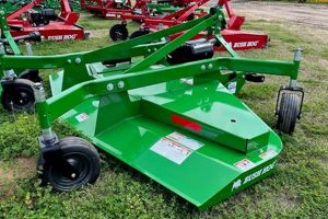
A visual representation illustrating the routing of the drive belt on a Land Pride finish mower is a critical resource for maintenance and repair. These diagrams detail the precise path the belt must follow around pulleys, idlers, and the mower deck spindle in order to ensure proper functionality. They typically include labels identifying each component involved in the belt system and directional arrows to indicate the correct belt orientation.
The availability of these schematics is essential for efficient servicing, minimizing downtime and potentially preventing costly repairs. Proper belt installation, guided by these layouts, guarantees optimal power transfer from the tractor’s power take-off (PTO) to the mower’s blades. Furthermore, using these illustrations for reference ensures the correct belt tension, reducing slippage and promoting consistent cutting performance. Historically, such information was often found within the operator’s manual, but is increasingly accessible online from manufacturers and parts suppliers.
Understanding the specifics presented within such a schematic is vital for proper mower upkeep. The following sections will delve into the common types of illustrations available, how to interpret them accurately, troubleshooting belt issues using the diagrams, and where to locate these helpful aids.
Guidance for Utilizing Drive Belt Schematics
The following recommendations aim to assist in the effective use of drive belt illustrations for Land Pride finish mowers.
Tip 1: Refer to the Correct Model Diagram: Always verify the schematic corresponds precisely to the Land Pride finish mower’s model number. Variances between models can result in inaccurate belt routing and subsequent operational failures.
Tip 2: Inspect Belt Condition Before Installation: Before fitting a new belt, examine it for any pre-existing damage, such as cuts, abrasions, or signs of deterioration. A compromised belt will likely fail prematurely, rendering the layout irrelevant.
Tip 3: Pay Attention to Pulley Alignment: Misaligned pulleys induce uneven wear on the belt, decreasing its lifespan and increasing the likelihood of slippage. Ensure all pulleys are properly aligned both horizontally and vertically, as indicated within the component illustration.
Tip 4: Verify Belt Tension After Installation: Insufficient or excessive belt tension can lead to operational problems. Consult the equipment’s specifications to determine the optimal tension for the drive belt following installation.
Tip 5: Note Idler Pulley Function: Idler pulleys maintain proper belt tension and routing. Confirm that idler pulleys are functioning smoothly and are free from any binding or excessive play, as observed in the layout.
Tip 6: Clean Pulleys Before Belt Replacement: Accumulation of debris on pulleys affects grip and can cause belt wear. Before installing a new belt, clean each pulley thoroughly with a wire brush and appropriate solvent.
Tip 7: Keep a Copy of the Diagram Accessible: Maintain a readily available copy of the mower’s diagram, either physically or digitally, to aid in troubleshooting and maintenance procedures. This ensures prompt reference when needed.
Adhering to these guidelines facilitates proper belt installation and maintenance, optimizing the Land Pride finish mower’s performance and longevity.
The subsequent discussion will provide information on where to find the proper belt diagrams for various Land Pride finish mower models.
1. Model Specificity
The principle of model specificity is paramount when utilizing a belt diagram for a Land Pride finish mower. These mowers are manufactured in various configurations, each possessing a potentially unique belt arrangement. The validity of the illustrative guide is entirely contingent upon its precise correspondence with the mower’s model number and series.
- Diagram Relevancy
A belt diagram is only pertinent if it directly mirrors the belt routing configuration of the specific mower model. Employing a diagram intended for a dissimilar model could result in incorrect belt placement, leading to operational failure and potential component damage. Diagram relevancy is often verifiable through cross-referencing the mower’s serial number with the manufacturer’s database.
- Pulley Arrangement Variations
Even subtle differences in mower models can manifest as significant variations in pulley placement and quantity. The diagram must accurately depict the number, size, and location of all pulleys and idlers in the belt system. A mismatch in pulley arrangement will render the diagram useless and could lead to improper belt tensioning.
- Belt Length Discrepancies
Model variations can require different belt lengths. A diagram tailored to a specific model will specify the correct belt length needed for optimal performance. Using a belt length prescribed by an incorrect diagram will likely result in either excessive slippage (if too long) or undue stress on the bearings and drive components (if too short).
- Tensioner Mechanism Compatibility
The type and placement of the belt tensioner can vary across models. The diagram should clearly illustrate the tensioner’s location and adjustment mechanism. An incompatible diagram could lead to improper tensioner settings, causing belt wear and reduced cutting efficiency.
Failing to adhere to the principle of model specificity when consulting a Land Pride finish mower belt diagram can negate the diagram’s utility and potentially introduce operational hazards. Therefore, precise model verification is the initial and most critical step in the maintenance process.
2. Belt Routing
Belt routing, the specific path a drive belt follows around pulleys and idlers, is the core information conveyed by a schematic for a Land Pride finish mower. This routing determines the proper transfer of power from the tractor’s power take-off (PTO) to the mower’s spindles, ensuring efficient blade rotation. Consequently, the accuracy and clarity of the representation of belt routing within the diagram are paramount for correct belt installation and mower operation.
- Correct Engagement
The illustration distinctly shows how the belt engages with each pulley, including the direction of wrap and contact points. Correct engagement ensures proper torque transfer and minimizes slippage. Deviations from the illustrated routing will likely result in the blades failing to reach optimal speed, leading to an uneven cut. For instance, an incorrect routing around the PTO pulley may cause the blades to turn too slowly.
- Idler Pulley Functionality
Belt routing depictions highlight the role of idler pulleys in maintaining belt tension and preventing belt deflection. The diagram specifies the sequence in which the belt passes around the idlers and their relative position to the drive pulleys. Improper routing concerning idler pulleys often leads to belt vibration, premature wear, and reduced mower performance. This directly impacts cut quality and overall efficiency.
- Belt Tension Side
The diagram implicitly defines the tension side and slack side of the belt. The tension side is the portion of the belt under the greatest load, responsible for transmitting power. Accurate routing ensures the tension side is properly aligned and supported by the appropriate pulleys. In contrast, the slack side benefits from correct idler placement. An incorrect arrangement can compromise the structural integrity of the belt due to uneven stress distribution.
- Obstacle Avoidance
Belt routing must consider the physical constraints of the mower deck and associated components. The diagram shows how the belt avoids obstructions, such as support brackets and discharge chutes. This clearance is essential to prevent chafing, binding, or other forms of physical damage to the belt. Should the prescribed routing not be followed, these collisions can cause catastrophic belt failure, and mower damage.
The effective communication of belt routing details within the Land Pride finish mower diagram directly affects the ability to properly install, maintain, and troubleshoot the mower’s drive system. A clear and accurate depiction of the belt’s pathway allows for optimized performance, reduced downtime, and prolonged component life. Therefore, prioritizing the understanding and application of the routing information provided by the illustration is crucial for any maintenance procedure.
3. Tension Accuracy
Tension accuracy is an indispensable element when utilizing a Land Pride finish mower belt diagram. Proper belt tension is essential for efficient power transfer, belt longevity, and overall mower performance. The diagram serves as a visual guide to ensure that the correct tension is achieved, preventing premature wear and operational failures.
- Belt Slippage Prevention
Insufficient belt tension allows the belt to slip on the pulleys, reducing the mower’s cutting efficiency and potentially damaging the belt and pulleys due to increased friction and heat. The diagram, in conjunction with the mower’s service manual, specifies the appropriate tension range, ensuring adequate grip and preventing slippage under load. For example, a correctly tensioned belt will maintain consistent blade speed even when mowing through thick grass, while an undertensioned belt will exhibit reduced speed and increased wear.
- Bearing Load Management
Excessive belt tension places undue stress on the bearings of the pulleys and spindles, leading to premature bearing failure. The diagram assists in identifying the correct belt routing, which influences the overall tension on the system. Adhering to the routing ensures that tension is distributed evenly, minimizing stress on individual components. For instance, incorrect routing can concentrate tension on a single pulley, accelerating bearing wear and potentially leading to catastrophic failure.
- Belt Life Optimization
Maintaining accurate belt tension significantly extends the operational lifespan of the belt. Overtensioning causes the belt to stretch and crack prematurely, while undertensioning leads to slippage and abrasion. The diagram provides a visual reference for proper belt placement and tensioner adjustment, allowing for precise calibration. Regular inspections, guided by the diagram, can identify potential tension issues before they result in belt failure, reducing maintenance costs and downtime.
- Power Transmission Efficiency
Optimal power transfer from the tractor’s PTO to the mower deck depends on correct belt tension. A properly tensioned belt ensures minimal power loss due to slippage, allowing the mower to operate at its designed efficiency. The diagram aids in verifying that the belt is correctly seated in the pulley grooves and that the tensioner is functioning as intended. Efficient power transmission translates to a cleaner cut, reduced fuel consumption, and improved overall mowing performance.
These facets demonstrate the critical role of tension accuracy in the context of a Land Pride finish mower. The belt diagram serves as a foundational tool for achieving and maintaining the correct tension, ultimately leading to improved performance, extended component life, and reduced operational costs. Neglecting tension accuracy, even when following the diagram for belt routing, can negate many of the diagram’s benefits, highlighting the interconnectedness of these maintenance aspects.
4. Component Identification
Component identification is an integral element of any layout related to the belt system of a Land Pride finish mower. Accurate identification of each component pulleys, idlers, tensioners, and spindles is crucial for correct belt routing, troubleshooting, and maintenance. The layout serves as a visual key, enabling technicians and operators to pinpoint specific parts within the system, facilitating efficient repairs and adjustments.
- Pulley Differentiation
The layout must differentiate between drive pulleys, idler pulleys, and driven pulleys. Drive pulleys are directly connected to the power source, while idler pulleys guide and tension the belt. Driven pulleys transfer power to the mower blades. Accurate identification ensures the belt is routed correctly around each pulley type, optimizing power transmission and minimizing slippage. Failure to distinguish between pulley types can result in improper belt tensioning and reduced cutting performance. For instance, misidentifying an idler pulley as a drive pulley could lead to incorrect belt engagement and potentially damage the mower’s drive system.
- Idler Pulley Variants
Within the category of idler pulleys, there exist variations in design and function, such as flat idlers, v-groove idlers, and spring-loaded tensioner idlers. The layout needs to specify the type of idler pulley at each location within the belt path. Correct identification is essential because each idler type serves a specific purpose in maintaining belt tension and preventing belt deflection. Using the wrong type of idler pulley can lead to increased belt wear and reduced mower efficiency. For example, substituting a flat idler for a v-groove idler could cause the belt to ride improperly, leading to premature wear and potential failure.
- Tensioner Assembly Recognition
The tensioner assembly is responsible for maintaining proper belt tension. The layout should depict the location and type of tensioner used, whether it is a spring-loaded arm, a manual adjustment mechanism, or another design. Accurate recognition of the tensioner assembly is crucial for performing tension adjustments and troubleshooting tension-related issues. Misidentification can lead to improper tensioning, resulting in belt slippage or excessive bearing load. For instance, an inability to correctly identify the adjustment point on a manual tensioner could lead to overtightening or undertightening the belt, affecting mower performance and belt life.
- Spindle Assembly Clarification
The spindle assemblies, which house the mower blades, are critical components in the belt drive system. The layout clarifies the position of the spindle pulleys relative to the other components. Proper identification of these is essential for verifying correct belt alignment and ensuring efficient power delivery to the blades. Incorrect alignment or damage to the spindle pulleys impacts cut quality, and can lead to increased vibration and potential spindle bearing failure. For instance, if the layout isn’t properly read and the alignment of the spindle pulleys isn’t checked, the result could be unnecessary spindle wear and potential failure.
The effective component identification within a Land Pride finish mower’s layout allows for precise maintenance and troubleshooting. By clearly delineating each part and its function, the layout empowers users to perform repairs, adjustments, and inspections with greater accuracy and efficiency. The success of any maintenance task hinges on correctly identifying the components involved and understanding their role within the belt drive system.
5. Safe Operation
Safe operation of a Land Pride finish mower is intrinsically linked to a thorough understanding and correct application of the belt diagram. This diagram is not merely a guide to belt routing, but a fundamental component in ensuring the mower operates within established safety parameters.
- Belt Guard Integrity
The diagram aids in ensuring correct belt routing, which is crucial for proper belt guard installation and functionality. Belt guards are designed to prevent accidental contact with the moving belt and pulleys. If the belt is not routed according to the diagram, the guards may not fit correctly or provide adequate protection, increasing the risk of injury. For instance, an improperly routed belt may protrude beyond the guard’s intended coverage area, exposing the operator or bystanders to a hazardous situation. Maintenance should always verify guard fitment after belt service.
- Minimizing Projectile Hazards
Incorrect belt installation, stemming from a misinterpreted diagram, can lead to belt failure during operation. A failing or broken belt can become a dangerous projectile, posing a significant risk of injury to the operator and those nearby. Proper adherence to the routing and tension specifications outlined in the diagram reduces the likelihood of such failures, thereby minimizing this projectile hazard. Regular inspection using diagram as a reference and belt replacement at recommended intervals is crucial to reduce the likelihood of this outcome.
- Preventing Entanglement Risks
The layout provides visual guidance for keeping clothing and other loose items clear of the moving belt and pulleys. Incorrect belt routing can create pinch points or increase the accessibility of the belt system, heightening the risk of entanglement. By following the diagram, operators can ensure that the belt is properly contained and that access to the moving parts is minimized. This is of paramount importance in preventing serious injuries. Prior to operation, a thorough visual inspection of the belt path is recommended to guarantee everything is within specification.
- Ensuring Correct PTO Engagement
The diagram indirectly contributes to safe PTO engagement by facilitating correct belt tension. A properly tensioned belt ensures smooth and controlled power transfer from the tractor’s PTO to the mower deck. Excessive or insufficient belt tension can lead to jerky or unpredictable PTO engagement, potentially causing loss of control or damage to the equipment. The user manual coupled with diagram should be referenced to ascertain that the PTO and associated belt are functioning as intended prior to operation.
In conclusion, the belt diagram for a Land Pride finish mower is a key component in promoting safe operation. By guiding correct belt routing, tensioning, and guard installation, the diagram reduces the risk of belt failure, projectile hazards, entanglement, and PTO-related incidents. Diligent adherence to the diagram’s specifications is essential for ensuring the safety of the operator and preventing damage to the equipment.
Frequently Asked Questions
The following addresses common inquiries and misconceptions regarding the utilization of belt layouts for Land Pride finish mowers.
Question 1: Where can the belt layout for a specific Land Pride finish mower model be located?
The belt layout is typically found within the operator’s manual for the respective mower. Alternatively, it may be available on the manufacturer’s website or from authorized Land Pride dealerships. Providing the mower’s model and serial number will aid in locating the correct schematic.
Question 2: What potential consequences arise from using an incorrect belt layout?
Employing an incorrect illustration can lead to improper belt routing, resulting in reduced mowing performance, accelerated belt wear, potential damage to pulleys and spindles, and an increased risk of belt failure. Furthermore, incorrect installation can compromise the functionality of safety guards.
Question 3: What level of expertise is required to properly interpret a belt layout?
While basic mechanical knowledge is beneficial, the layouts are generally designed to be straightforward. Familiarity with the terminology related to mower components, such as pulleys, idlers, and spindles, is advantageous. If uncertainty persists, consultation with a qualified mechanic is recommended.
Question 4: How often should the belt tension be checked, and how does the layout assist in this process?
Belt tension should be checked regularly, ideally before each mowing session or after every eight hours of operation. The layout indicates the location of the tensioner mechanism and provides visual guidance for assessing proper belt deflection. A belt tension gauge may be required for precise measurement.
Question 5: Is it permissible to deviate from the belt routing depicted in the illustration?
Deviation from the prescribed belt routing is strongly discouraged. The routing is engineered to optimize power transmission, maintain proper belt tension, and ensure safe operation. Any alteration to the routing can negatively impact mower performance and increase the risk of component failure or injury.
Question 6: What should be done if the belt keeps slipping even with correct tension according to the diagram?
If belt slippage persists despite proper tensioning, inspect the pulleys for wear or damage. Worn pulleys can reduce belt grip, leading to slippage. Replacement of worn pulleys is necessary to restore proper function. Verify correct belt type (width and length) is used. Incorrect belt profile or length will also lead to slippage, regardless of proper tension.
Accurate adherence to the belt layout and diligent maintenance practices are essential for ensuring the longevity and reliable operation of a Land Pride finish mower.
The succeeding section addresses troubleshooting prevalent belt-related issues.
Conclusion
The preceding analysis underscores the critical importance of the “land pride finish mower belt diagram” in the maintenance and safe operation of these machines. Its accurate interpretation directly impacts belt routing, tension accuracy, component identification, and overall system integrity. A failure to adhere to the layout’s specifications can precipitate operational inefficiencies, premature component failure, and heightened safety risks. The diagram serves as a foundational document for technicians and operators alike, guiding proper installation, troubleshooting, and preventative maintenance procedures.
Given the pivotal role of the belt diagram, its accessibility and understanding should be prioritized. Consistent reference to the proper diagram, coupled with a commitment to meticulous maintenance practices, is essential for maximizing the lifespan and ensuring the safe, reliable performance of Land Pride finish mowers. Continued emphasis on user education and readily available resources related to these layouts will contribute significantly to the longevity and safe operation of these machines in the field.


![Buy Premium Finishing Mower for Sale - [Brand] Edition Best Final Touch: Elevate Your Projects with Professional Finishing Buy Premium Finishing Mower for Sale - [Brand] Edition | Best Final Touch: Elevate Your Projects with Professional Finishing](https://bestfinaltouch.com/wp-content/uploads/2025/12/th-628-300x200.jpg)
