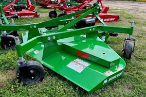
A visual representation detailing the components of a County Line finish mower is a crucial tool for maintenance and repair. This schematic, typically presented as a diagram, illustrates the arrangement of parts and their relationships within the mower’s assembly. An example includes a breakdown showing the spindle assembly, deck configuration, and belt routing, each labeled for identification.
Accessing and understanding this type of resource offers significant benefits. It facilitates accurate parts identification when ordering replacements, reduces downtime by enabling faster troubleshooting, and empowers users to perform basic repairs, potentially saving on professional service costs. Historically, these diagrams have evolved from simple line drawings to detailed exploded views, often incorporating part numbers and torque specifications.
The following sections will delve into how to locate these diagrams, interpret their symbols and notations, and utilize them effectively for maintaining the operational integrity of a County Line finish mower.
Successfully utilizing schematics for County Line finish mowers requires careful attention to detail. The following tips outline best practices for interpreting and applying the information found within these diagrams.
Tip 1: Acquire the Correct Diagram: Ensure the schematic matches the specific model and year of the County Line finish mower. Discrepancies can lead to incorrect part identification and assembly errors. Locate the model number on the mower’s frame and cross-reference it with available resources from the manufacturer or retailer.
Tip 2: Familiarize Yourself with Symbols and Conventions: Diagrams employ standardized symbols to represent hardware, fasteners, and specific components. Study the legend or key accompanying the diagram to accurately interpret these symbols. This prevents misidentification of parts and ensures proper reassembly.
Tip 3: Cross-Reference Part Numbers: Always verify part numbers listed on the diagram with the corresponding numbers in the parts catalog or online retailer. Discrepancies may indicate a superseded part or a component not compatible with the specific model. Double-checking avoids ordering incorrect replacements.
Tip 4: Note Orientation and Assembly Sequence: Pay close attention to the orientation of parts within the diagram and the recommended assembly sequence. Incorrect orientation or assembly order can lead to malfunctions or damage. Observe the exploded views and follow the indicated steps meticulously.
Tip 5: Consult Torque Specifications: The diagram may include torque specifications for critical fasteners. Adhere to these specifications when reassembling components. Over-tightening can damage threads or weaken parts, while under-tightening can lead to loosening and failure.
Tip 6: Consider Professional Assistance: If the diagram is unclear or the repair process is beyond one’s capabilities, seek assistance from a qualified mechanic. Attempting complex repairs without sufficient knowledge can result in further damage or injury.
Tip 7: Digital Resources: Many manufacturers and retailers provide digital versions of these schematics. These often include zoom functionality and interactive features for enhanced clarity. Utilize these digital resources when available.
Following these tips ensures accurate interpretation and application of the schematics, facilitating effective maintenance and repair of County Line finish mowers.
The concluding section will offer resources for locating diagrams and additional support information.
1. Identification accuracy
Identification accuracy is paramount when utilizing schematics for County Line finish mowers. The precision with which components are identified directly impacts the success of maintenance and repair efforts. The diagram serves as the primary reference for this identification process.
- Correct Part Numbering
The schematic provides specific part numbers for each component. Accurate cross-referencing of these numbers with parts catalogs or online retailers is essential. An incorrect part number leads to ordering an incompatible component, rendering repairs ineffective. For example, substituting a spindle with the wrong part number may result in improper fitment and subsequent equipment failure.
- Model-Specific Variations
County Line finish mowers exist in various models and configurations. Diagrams are model-specific, accounting for subtle differences in component design and arrangement. Using a schematic intended for a different model can result in misidentification of parts and incorrect reassembly. A deck reinforcement bracket from one model may not fit another, despite appearing similar in a generic illustration.
- Diagram Resolution and Clarity
The quality of the schematic itself impacts identification accuracy. Low-resolution or poorly reproduced diagrams can obscure details, making it difficult to distinguish between similar components. A fuzzy illustration of a spring may lead to confusion with a similar-sized bushing, resulting in incorrect replacement.
- Understanding Exploded Views
Schematics often utilize exploded views to illustrate the relative position and assembly order of components. Correctly interpreting these views is crucial for accurate identification and subsequent reassembly. Misunderstanding the exploded view of a belt tensioner may result in incorrect belt routing and reduced mower performance.
In conclusion, accurate identification, facilitated by a clear and model-specific County Line finish mower parts diagram, is the cornerstone of effective maintenance. Errors in this initial step cascade through the repair process, potentially leading to equipment damage and unnecessary expenses.
2. Model specificity
Model specificity is a critical factor when dealing with County Line finish mower parts diagrams. The efficacy of a diagram in aiding maintenance and repair is directly contingent upon its precise match with the mower’s specific model number. Failure to observe this principle can lead to significant errors in component identification and replacement.
- Component Variation Across Models
County Line finish mowers are manufactured in various models, each potentially featuring unique components or subtle design alterations. A diagram intended for one model may not accurately depict the parts used in another, even if the mowers appear superficially similar. For instance, the spindle assembly in a 54-inch model might differ significantly from that in a 60-inch model, rendering a generic diagram useless.
- Diagram Revisions and Updates
Manufacturers often introduce revisions to their mower designs over time. A diagram accurate for an older production run may not reflect changes implemented in later versions of the same model. It is therefore essential to ascertain the production date of the mower and ensure the diagram corresponds to that timeframe. A change in belt routing, for example, may necessitate a different diagram revision to avoid incorrect installation.
- Engine Compatibility and Configuration
Different County Line finish mower models may utilize different engines, each with its own unique set of parts. The diagram must accurately reflect the engine type and its associated components, such as belts, pulleys, and mounting hardware. An incorrect diagram could lead to ordering an incompatible engine belt or misidentifying a key engine component.
- Attachment and Accessory Compatibility
Some County Line finish mowers are designed to accommodate specific attachments or accessories. The diagram must account for these variations, illustrating the necessary components and their integration with the mower. Attempting to install an attachment using a diagram that does not account for its presence could lead to improper installation and potential damage.
The foregoing illustrates that model specificity is not merely a minor detail, but rather a fundamental requirement for effectively utilizing County Line finish mower parts diagrams. The consequences of neglecting this principle range from simple inconvenience to significant equipment damage and unsafe operating conditions. Proper identification of the mower model and procurement of the corresponding diagram are therefore essential steps in any maintenance or repair procedure.
3. Component visualization
Component visualization, in the context of County Line finish mower maintenance, refers to the ability to mentally construct a comprehensive image of the mower’s constituent parts, their spatial relationships, and their functions. This ability is significantly enhanced by a detailed parts diagram.
- Spatial Understanding
The diagram provides a visual representation of each component’s location relative to others within the mower’s assembly. This spatial awareness aids in disassembly and reassembly, preventing errors and ensuring proper functionality. For example, the diagram clarifies the precise positioning of the idler pulley relative to the mower deck and drive belt, ensuring correct belt tension and preventing premature wear.
- Functional Awareness
Visualizing the components enables an understanding of their individual roles within the overall operation of the mower. The diagram clarifies how each part contributes to the cutting process, drive system, or safety mechanisms. Recognizing the function of the anti-scalp rollers, for instance, allows for proactive maintenance to prevent damage to the turf and mower deck.
- Troubleshooting Efficiency
A strong mental image of the mower’s components facilitates more efficient troubleshooting. When a malfunction occurs, visualization assists in identifying the potential source of the problem and the affected parts. For example, a decrease in cutting performance might prompt the user to visually inspect the blades, belt, and spindle assembly based on the diagram’s representation.
- Parts Identification Accuracy
Clear component visualization improves the accuracy of parts identification when ordering replacements. By referencing the diagram, the user can confidently select the correct part number and avoid ordering incorrect or incompatible components. Visual confirmation that the new blade matches the diagram’s depiction of the original blade mitigates the risk of improper installation.
In summary, component visualization, facilitated by a well-defined County Line finish mower parts diagram, is a crucial skill for effective maintenance and repair. The diagram provides the visual framework for understanding the mower’s construction, function, and troubleshooting, leading to more efficient and accurate maintenance practices.
4. Assembly guidance
A County Line finish mower parts diagram serves as a primary source of assembly guidance, providing a visual roadmap for the correct arrangement and connection of components. The diagram illustrates the sequence in which parts should be joined, often employing exploded views to clarify the spatial relationship between each element. A lack of adherence to this guidance can lead to incorrect assembly, resulting in malfunctions or even equipment damage. For example, if the diagram indicates a specific order for installing the blade spindle components, deviating from this order could lead to improper blade alignment and a compromised cutting performance.
The information provided by the diagram is crucial for both initial assembly of a new mower and reassembly following repairs. The clarity and accuracy of the assembly guidance are directly dependent on the quality of the parts diagram itself. A well-designed diagram includes detailed annotations, torque specifications, and clear depictions of component orientation. This information is particularly important when dealing with complex assemblies such as the cutting deck or the drive system. Ignoring the assembly guidance provided by the diagram can lead to safety hazards, such as loose blades or improperly secured drive belts.
In conclusion, the County Line finish mower parts diagram is an indispensable tool for ensuring correct assembly. It acts as a visual manual, guiding the user through the process of correctly connecting the various components. While the diagram provides a framework for assembly, it is the user’s responsibility to carefully interpret and follow the guidance to ensure the mower operates safely and efficiently. Access to a clear and accurate diagram is therefore essential for successful assembly and maintenance of County Line finish mowers.
5. Repair facilitation
Repair facilitation, within the context of County Line finish mowers, hinges significantly on the availability and comprehension of detailed parts diagrams. These diagrams directly impact the efficiency and accuracy of repair procedures.
- Component Identification for Replacement
A parts diagram provides a clear visual representation of each component, alongside its corresponding part number. This expedites the process of identifying damaged or worn parts and ordering appropriate replacements. Without an accurate diagram, technicians may struggle to identify the correct part, leading to delays and potentially incorrect orders. For instance, discerning the difference between a specific bearing type in the spindle assembly is greatly simplified with a detailed diagram.
- Disassembly and Reassembly Guidance
The diagram often illustrates exploded views, revealing the order in which components should be disassembled and reassembled. This is particularly useful for complex assemblies, such as the gearbox or cutting deck. Following the sequence outlined in the diagram minimizes the risk of damaging components or incorrectly reassembling the mower. A mechanic can use the diagram to correctly reinstall the belt tensioner spring, ensuring proper belt tension and mower operation.
- Troubleshooting Assistance
Diagrams aid in diagnosing problems by allowing technicians to trace the connections between components. By visualizing the system, they can more easily identify potential points of failure. If the mower blades are not engaging, a parts diagram can assist in tracing the linkage from the engagement lever to the blade spindle, facilitating a more focused diagnosis. This helps in limiting downtime.
- Accessibility of Information
The wide distribution and accessibility of parts diagrams are also key for efficient repair. In this digital age, readily-accessible online diagrams empower DIY repair and remote technicians alike. The fact that operators have these resources enhances repair facilitation, no matter how complex the issue may be.
The preceding elements emphasize the fundamental role parts diagrams play in the repair process for County Line finish mowers. By providing clear visuals, accurate part numbers, and assembly guidance, these diagrams contribute significantly to efficient and accurate maintenance and repair.
6. Parts sourcing
The process of parts sourcing for County Line finish mowers is inextricably linked to the availability and accuracy of its parts diagram. This visual representation provides the essential information required to identify and procure the correct replacement components. The diagram serves as a crucial reference point, mitigating the risk of ordering incorrect parts and ensuring compatibility with the specific mower model. A well-detailed diagram includes part numbers, component descriptions, and exploded views, facilitating precise identification and streamlining the parts ordering process. For example, a damaged spindle assembly can be accurately identified on the diagram, allowing the user to source the exact replacement from a supplier.
Parts diagrams also enable effective comparison shopping. By providing detailed specifications and dimensions, the diagram facilitates the assessment of aftermarket alternatives and ensures that replacement parts meet the required performance standards. Access to a parts diagram empowers users to evaluate various suppliers and make informed purchasing decisions based on price and availability. Furthermore, the diagram aids in identifying related components that may require replacement simultaneously, such as belts or bearings, promoting comprehensive maintenance and preventing future breakdowns. An example of this can be the identification of a related belt part number to be added when replacing a motor pulley that is causing the belt to break during use.
In conclusion, the County Line finish mower parts diagram is an indispensable tool for parts sourcing. It provides the necessary visual and technical information to accurately identify, source, and procure replacement components, ultimately contributing to efficient maintenance, reduced downtime, and extended equipment lifespan. Challenges remain in maintaining up-to-date diagrams that reflect design changes and model variations, highlighting the importance of sourcing diagrams directly from the manufacturer or authorized retailers. Understanding the critical role of the parts diagram enhances the overall maintenance and repair strategy for County Line finish mowers.
7. Troubleshooting aid
A County Line finish mower parts diagram functions as a crucial troubleshooting aid by providing a visual framework for understanding the mower’s mechanical systems. When a malfunction occurs, the diagram allows for systematic identification of potential causes by illustrating the relationships between various components. For example, if the mower blades fail to engage, the parts diagram can assist in tracing the engagement mechanism from the control lever to the blade spindles, helping to pinpoint the source of the problem, such as a broken cable or a faulty clutch. The diagram provides a clear overview that facilitates efficient diagnostic work.
The detailed nature of the diagram aids in differentiating between similar components, preventing misdiagnosis. A parts diagram displays the specific orientation and connections of belts, pulleys, and springs, crucial for identifying parts that have become dislodged or damaged. If a belt keeps slipping off a pulley, the diagram can confirm proper belt routing and identify the correct tensioner spring. The parts diagram becomes an invaluable resource for confirming the proper arrangement of parts and the validity of potential solutions.
The utility of the parts diagram as a troubleshooting aid lies in its ability to bridge the gap between observed symptoms and underlying mechanical issues. By providing a clear visual representation of the mower’s construction, the diagram enhances diagnostic accuracy and reduces the time required to resolve mechanical problems. Maintaining accessible and accurate parts diagrams is, therefore, a critical factor in ensuring the reliable operation and longevity of County Line finish mowers.
Frequently Asked Questions Regarding County Line Finish Mower Parts Diagrams
This section addresses common inquiries related to obtaining, interpreting, and utilizing parts diagrams for County Line finish mowers. It aims to provide clarity and ensure users can effectively leverage these diagrams for maintenance and repair.
Question 1: Where can a County Line finish mower parts diagram be located?
Parts diagrams are typically available from several sources. The official manufacturer’s website is a primary source, offering model-specific diagrams in PDF format. Authorized County Line dealers may also provide diagrams, either in print or digital form. Online parts retailers frequently host diagrams as part of their parts lookup systems. When searching online, specifying the exact model number of the mower is essential.
Question 2: How is the correct diagram version determined for a specific mower?
The correct diagram version corresponds to the mower’s model number and production year. The model number is generally found on a decal affixed to the mower’s frame. After locating the model number, consult the manufacturer’s website or the mower’s operator’s manual to identify the applicable diagram revision. If multiple revisions exist for the same model number, production date information will be necessary to pinpoint the correct diagram.
Question 3: What information does a typical County Line finish mower parts diagram contain?
A typical diagram includes an exploded view of the mower assembly, illustrating the relative position of each component. Each component is labeled with a unique part number and a brief description. The diagram may also include torque specifications for critical fasteners and assembly notes providing guidance on proper installation procedures.
Question 4: How are part numbers used in conjunction with the parts diagram?
The part numbers listed on the diagram are used to identify and order replacement components. After identifying the desired part on the diagram, the corresponding part number is used to search for the part at authorized dealers or online retailers. Accurate part number verification is crucial to ensure compatibility.
Question 5: What are the common symbols found on these parts diagrams?
Parts diagrams employ standardized symbols to represent various components and assembly methods. Common symbols include representations of fasteners (bolts, nuts, screws), seals, bearings, and electrical connectors. A legend or key is typically included with the diagram to explain the meaning of each symbol. Understanding these symbols enhances the comprehension of the diagram’s information.
Question 6: What should be done if the parts diagram is unclear or difficult to interpret?
If the diagram is unclear, consulting the operator’s manual may provide additional clarification. Online forums and communities dedicated to lawn mower maintenance can offer assistance and insights. Contacting an authorized County Line dealer is also a viable option; dealers possess specialized knowledge and can provide expert guidance. In cases of significant ambiguity, seeking professional assistance is advisable.
Accurate identification, correct diagram usage, and appropriate parts sourcing are crucial elements for maintaining County Line finish mowers. The parts diagram is an essential resource for facilitating these activities.
The next section will explore resources for obtaining additional support and information.
Conclusion
This exploration has emphasized the significance of the county line finish mower parts diagram as a central resource for maintenance and repair. It clarifies component identification, facilitates proper assembly, aids in troubleshooting, and streamlines parts sourcing. A thorough understanding of the diagram’s contents and effective utilization of its information are essential for maintaining the operational integrity of the machinery.
Continued advancements in diagram accessibility and accuracy will further enhance the ability to maintain and repair these mowers. Users are encouraged to prioritize acquiring and diligently studying the appropriate diagrams for their specific mower models to ensure safe and effective operation. Proper utilization of the county line finish mower parts diagram remains fundamental to prolonged equipment lifespan and optimized performance.


![Buy Premium Finishing Mower for Sale - [Brand] Edition Best Final Touch: Elevate Your Projects with Professional Finishing Buy Premium Finishing Mower for Sale - [Brand] Edition | Best Final Touch: Elevate Your Projects with Professional Finishing](https://bestfinaltouch.com/wp-content/uploads/2025/12/th-628-300x200.jpg)
