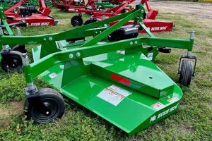
A visual representation detailing the constituent components of a Land Pride finish mower, arranged to show their relationships and facilitate identification, is a crucial resource. This schematic illustration aids in locating specific components for replacement, repair, or general maintenance procedures. For example, such a representation might show the location of a spindle assembly, belt, or blade relative to the mower deck and other internal parts.
The availability of such a visual tool provides several advantages. It simplifies the process of ordering correct replacement items, minimizing downtime. Furthermore, it provides a structured understanding of the equipment’s assembly, potentially reducing the need for professional servicing in some cases. Historically, these representations evolved from hand-drawn illustrations to digitally produced diagrams, reflecting advancements in technical documentation.
The remainder of this explanation will address key aspects related to effectively utilizing such a schematic, including navigating the diagram, identifying part numbers, understanding common mower components, and locating resources for obtaining these visual aids.
The following are guidelines for effectively utilizing a Land Pride finish mower component schematic to ensure accurate part identification and facilitate maintenance.
Tip 1: Consult the Correct Model Diagram: Ensure the diagram corresponds precisely to the mower’s model number and serial number. Using an incorrect diagram can lead to misidentification of components and incompatibility issues during replacement.
Tip 2: Locate the Exploded View: The exploded view typically presents the complete mower disassembled, displaying the spatial relationships between individual parts. Begin with this view for a general overview of the component arrangement.
Tip 3: Identify Part Numbers: Each component in the schematic is assigned a unique part number. Note this number precisely when ordering replacements. Double-check the number against the parts list provided with the diagram.
Tip 4: Understand Subassemblies: Some diagrams depict subassemblies as individual units. Pay attention to these, as they might require ordering multiple parts together for complete repair.
Tip 5: Utilize Magnification Tools: For detailed schematics, consider using digital magnification tools or a printed magnifying glass to examine smaller components and their associated part numbers with greater clarity.
Tip 6: Reference the Parts List: Cross-reference the identified part number with the parts list accompanying the diagram. The parts list provides a detailed description of the component, including its dimensions and material specifications.
Tip 7: Note Revision Dates: Schematics are periodically updated to reflect design changes. Confirm the revision date of the diagram matches the manufacturing date of the mower, if available, to ensure accuracy.
By adhering to these guidelines, the process of identifying and sourcing replacement components for a Land Pride finish mower becomes significantly more efficient, reducing potential errors and minimizing downtime.
The following sections will delve into specific aspects of mower maintenance and component replacement, building upon the knowledge gained from interpreting the component schematic.
1. Model Specificity
Model specificity is paramount when utilizing a component schematic for Land Pride finish mowers. These schematics are meticulously crafted to reflect the unique design and arrangement of components within each specific mower model. Employing a schematic intended for a different model, even one seemingly similar, can lead to significant errors in parts identification and subsequent repair attempts. The internal configuration, component dimensions, and even the type of hardware used can vary considerably between models. This variation means that a part identified on an incorrect schematic may not physically fit or function correctly within the actual mower.
For example, if a user possesses a Land Pride FDR1660 finish mower but mistakenly uses the component schematic for an FDR1540 model, they might incorrectly identify the spindle assembly or blade size. Ordering parts based on this incorrect schematic would result in receiving components incompatible with the FDR1660, rendering the repair impossible without sourcing the correct parts. This situation incurs additional costs, delays the repair process, and potentially causes further damage if the incorrect parts are forced into place. Furthermore, subtle differences in component design can affect mower performance and safety. Using mismatched parts, even if they appear to fit, can compromise the mower’s operational integrity.
Therefore, verifying that the component schematic aligns precisely with the Land Pride finish mower’s model number and, if available, its serial number is a critical initial step. The model number is typically located on a plate or sticker affixed to the mower frame. Neglecting this verification can result in wasted time, money, and potential damage. Correct model specificity is not simply a best practice; it is a fundamental requirement for effective maintenance and repair utilizing Land Pride finish mower component schematics.
2. Exploded Views
Exploded views are integral components of Land Pride finish mower component schematics. These diagrams depict the mower disassembled, with each component spatially separated to illustrate its position and relationship to other parts. This visual presentation serves as a foundational reference for understanding the mower’s construction. The absence of an exploded view would significantly hinder the user’s ability to identify component locations and understand the order of assembly or disassembly. For instance, when replacing a spindle, an exploded view clarifies the positioning of bearings, seals, and the spindle housing itself, relative to the mower deck. Without it, the reassembly process becomes substantially more complex and prone to error.
The practical significance lies in facilitating efficient repairs and maintenance. Exploded views often include callouts with corresponding part numbers, linking visual identification directly to ordering information. This connection drastically reduces the chances of procuring incorrect parts. Consider a scenario where a user needs to replace a damaged belt. By consulting the exploded view, the user can not only identify the belt’s location but also ascertain the correct routing path around pulleys and idlers. This understanding is critical for ensuring proper belt tension and preventing premature wear. Furthermore, exploded views aid in understanding subassemblies, clarifying how multiple smaller components fit together to form a larger, functional unit.
In summary, exploded views are not merely supplementary illustrations; they are essential elements of a Land Pride finish mower component schematic. They provide a clear, visual representation of the mower’s construction, facilitating accurate parts identification, simplifying assembly procedures, and ultimately reducing the time and resources required for maintenance and repair. The clarity offered by exploded views directly impacts the efficiency and accuracy of any work done on the finish mower.
3. Part Number Accuracy
The validity of a Land Pride finish mower component schematic is fundamentally dependent on the precision of its part numbers. Inaccuracies in these numbers directly compromise the schematic’s utility, leading to incorrect parts orders and subsequent equipment downtime.
- Unique Component Identification
Each component within a Land Pride finish mower is assigned a distinct part number. This alphanumeric code serves as the primary means of identifying and ordering the correct replacement item. The component schematic uses these numbers to link visual representations of parts to their specific ordering information. Erroneous part numbers sever this connection, rendering the diagram useless for procurement purposes.
- Compatibility Assurance
Part numbers guarantee compatibility between replacement components and the mower. A schematic with incorrect part numbers can mislead users into ordering parts that do not fit or function correctly, potentially causing further damage to the equipment. Compatibility issues often arise when a part number differs by only a single digit, highlighting the critical importance of accuracy.
- Preventing Mismatched Parts
Land Pride finish mowers are complex machines comprised of numerous interconnected parts. Using an incorrect part can disrupt the mower’s operational balance and lead to premature wear or failure of other components. Accurate part numbers on the component schematic are crucial for maintaining the mower’s original design specifications and ensuring optimal performance.
- Streamlining Ordering Processes
Dealers and suppliers rely on part numbers to fulfill orders efficiently and accurately. When a component schematic contains errors, it introduces ambiguity into the ordering process, resulting in delays, increased costs, and potential frustration for the equipment owner. Reliable part numbers facilitate a streamlined and error-free parts acquisition experience.
In summary, the accuracy of part numbers is not merely a detail but a cornerstone of effective Land Pride finish mower maintenance. A flawed component schematic, riddled with incorrect part numbers, effectively nullifies its purpose, leading to potential equipment damage, increased expenses, and operational inefficiencies. Therefore, meticulous attention to detail in verifying part numbers is indispensable for maximizing the value of a component schematic.
4. Subassembly Identification
Subassembly identification within a Land Pride finish mower component schematic is essential for accurately understanding and addressing maintenance requirements. These schematics often represent the mower’s structure not just as individual components, but as integrated units, or subassemblies, which are themselves composed of multiple parts. The proper recognition of these subassemblies is crucial for efficient parts ordering and repair execution.
- Efficient Parts Acquisition
Subassemblies, such as spindle assemblies or gearbox units, are often replaced as a whole, rather than piecemeal. The parts diagram clearly delineates these units, allowing a technician to order the complete subassembly using a single part number, streamlining the procurement process and ensuring all necessary components are included. This avoids the need to individually identify and order each component within the subassembly.
- Simplified Repair Procedures
Understanding subassemblies simplifies repair procedures by providing a pre-defined unit for replacement. Instead of disassembling and reassembling numerous individual parts, the technician can replace the entire subassembly, reducing labor time and the risk of errors. For example, a faulty caster wheel assembly is more easily addressed by replacing the entire unit, as shown in the diagram, rather than attempting to repair individual bearings or bushings.
- Accurate Diagnosis of Issues
The component schematic’s representation of subassemblies aids in diagnosing the source of a problem. If the diagram clearly illustrates a self-contained subassembly and that unit is malfunctioning, the technician can readily identify the problematic area. This targeted approach reduces troubleshooting time and avoids unnecessary disassembly of other components.
- Ensuring Compatibility
Replacing a subassembly guarantees compatibility between its constituent parts. By ordering the complete unit as represented in the schematic, the technician avoids the risk of using mismatched or incompatible components. This is particularly important for complex subassemblies, such as gearboxes, where precise tolerances and component interactions are critical for proper operation.
In conclusion, the accurate identification of subassemblies within a Land Pride finish mower’s parts diagram directly impacts the efficiency and accuracy of maintenance and repair operations. By recognizing these pre-defined units, technicians can streamline parts ordering, simplify repair procedures, facilitate accurate diagnoses, and ensure compatibility between components, ultimately minimizing downtime and optimizing mower performance.
5. Diagram Revision Dates
Diagram revision dates are a critical, yet often overlooked, element within the context of a Land Pride finish mower component schematic. These dates provide a crucial indicator of the diagram’s accuracy and applicability to a specific mower, directly impacting the efficacy of maintenance and repair efforts.
- Reflecting Engineering Changes
Land Pride finish mower designs undergo periodic revisions to improve performance, durability, or manufacturability. These changes necessitate updates to the component schematics. The revision date signifies when the diagram was last updated to reflect these engineering modifications. For instance, if a mower deck reinforcement was added in 2022, a schematic with a revision date prior to 2022 would not accurately depict this feature, potentially leading to incorrect parts orders or improper repair procedures.
- Component Supersession Tracking
Manufacturers often supersede components, replacing older versions with improved or more readily available alternatives. The parts diagrams are updated to reflect these supersessions. A newer revision date ensures that the schematic incorporates the latest component supersession information. Failure to consult the revision date could result in ordering an obsolete part, hindering the repair process. An example is the substitution of a belt with improved material, a change that necessitates using the updated part number listed in the latest revision of the component schematic.
- Maintaining Parts Interchangeability
Component interchangeability can be affected by design modifications. A change to a mounting bracket, for instance, might render an older component incompatible. Diagram revision dates are crucial for determining whether parts are interchangeable between different production runs of the same mower model. A schematic with a more recent revision date will accurately indicate any interchangeability limitations, preventing the use of incompatible components and potential equipment damage.
- Ensuring Hardware Specifications
Hardware specifications, such as bolt sizes and torque values, can also be subject to change. The most current schematic revision incorporates any alterations to these specifications. Using an outdated diagram might lead to employing incorrect hardware, compromising the structural integrity of the repair and potentially causing component failure. An example would be a change in the grade of bolt used in the spindle assembly, which would necessitate the use of the updated bolt specified in the current schematic revision.
The diagram revision date is, therefore, not simply a date but a crucial identifier that signifies the schematic’s compatibility with a given Land Pride finish mower. Consulting the revision date, comparing it against the mower’s manufacturing date (if available), and ensuring that the most current schematic is used are all essential steps in preventing errors and maximizing the effectiveness of maintenance and repair efforts.
6. Component Location
The primary function of a Land Pride finish mower component schematic is to elucidate the location of each individual part within the overall assembly. A parts diagram, regardless of its accuracy in other areas, is rendered substantially less effective if it fails to precisely depict the physical positioning of its constituent parts. The consequence of an unclear or inaccurate depiction of component location is a dramatically increased difficulty in both diagnosing issues and executing repairs. For example, if the diagram incorrectly places the idler pulley relative to the drive belt and spindle, the technician may waste considerable time searching for the pulley in the wrong area, potentially disassembling other components unnecessarily. Without a clear understanding of where each component resides, even simple repairs become unduly complicated.
The importance of accurate component location is highlighted when dealing with internal or obscured parts. In the case of a Land Pride finish mower’s gearbox, for example, the schematic must clearly show the relative position of gears, bearings, and seals. If the diagram obscures these locations or presents them ambiguously, identifying a faulty gear or replacing a leaking seal becomes significantly more challenging. Furthermore, the precise location of components often dictates the order of assembly and disassembly. The diagram must accurately portray this sequence to prevent damage to components during maintenance procedures. Incorrect depictions of component placement can lead to attempts to remove parts in the wrong order, potentially resulting in damage or breakage, further increasing repair costs and downtime.
In conclusion, the accurate and unambiguous depiction of component location is not merely a supplementary feature of a Land Pride finish mower component schematic; it is a fundamental requirement for its successful application. Without a clear understanding of where each part is physically situated within the assembly, the diagram’s value is severely diminished, leading to increased troubleshooting time, higher repair costs, and a greater risk of equipment damage. The component location is critical.
7. Hardware Details
Hardware details, encompassing specifications such as size, thread pitch, material grade, and quantity of fasteners (bolts, nuts, washers, screws, etc.), are intrinsically linked to a Land Pride finish mower component schematic. These details are not merely supplementary information; they are essential for accurate parts identification and successful reassembly of the equipment. The component schematic provides the visual context, illustrating where each piece of hardware is used. However, the ‘Hardware Details’ section provides the granular information necessary to procure the correct replacement. An incomplete or inaccurate representation of hardware elements can result in structural instability, operational failure, or even safety hazards. For example, using an incorrect bolt size for attaching a blade spindle can lead to loosening during operation, potentially causing blade detachment and projectile hazards. The schematic ensures that the correct part is placed in the right location, the hardware details ensure the correct fastener is used to secure it.
The practical significance of understanding this connection manifests during maintenance and repair scenarios. When replacing a worn-out bearing, the schematic indicates its location within the spindle assembly, while the accompanying hardware details specify the exact type and number of bolts required to reassemble the housing. Omission of these details necessitates guesswork, potentially resulting in the use of undersized or weakened fasteners that compromise the integrity of the assembly. Similarly, knowing the correct torque specifications, often linked to hardware details in supporting documentation, is crucial for achieving proper clamping force without over-tightening and stripping threads. Digital versions of the Land Pride finish mower component schematic often allow direct linking from the visual representation of a fastener to its specific part number and detailed attributes, further simplifying the process.
In summary, the symbiosis between a Land Pride finish mower component schematic and its associated hardware details cannot be overstated. The schematic offers a visual guide to component placement, while the hardware details provide the precise specifications necessary for correct installation and secure operation. Neglecting either aspect compromises the integrity of the repair and can have significant consequences for equipment performance and safety. Integrating this understanding into routine maintenance practices contributes to prolonging the lifespan of the mower and reducing the risk of operational failures. A challenge lies in ensuring these schematics and hardware details are readily accessible and consistently updated to reflect ongoing design modifications.
Frequently Asked Questions
The following section addresses common inquiries regarding Land Pride finish mower component schematics, providing clarification and guidance on their use and interpretation.
Question 1: Why is it critical to use the exact parts diagram for my Land Pride mower model?
Land Pride offers a range of finish mower models, each with specific designs and component configurations. A diagram intended for a different model may depict incompatible parts or an inaccurate assembly, leading to incorrect orders and failed repairs.
Question 2: Where can the model number of a Land Pride finish mower be found?
The model number is typically located on a metal plate or sticker affixed to the mower frame. The precise location may vary depending on the specific model, but it is generally found near the hitch or on the mower deck.
Question 3: What is the significance of the revision date on a component schematic?
The revision date indicates when the diagram was last updated to reflect design changes or component supersessions. Using a diagram with an outdated revision date may result in ordering obsolete parts or failing to account for engineering modifications.
Question 4: Are exploded views essential components of a Land Pride finish mower diagram?
Yes, exploded views are highly beneficial. They provide a visual representation of the mower disassembled, illustrating the spatial relationships between components. This facilitates accurate parts identification and simplifies assembly procedures.
Question 5: How should part numbers on a component schematic be used to order replacement parts?
The part number should be cross-referenced with the parts list accompanying the diagram. This ensures that the correct part is ordered and that any necessary hardware or accessories are included.
Question 6: What are the potential consequences of using incorrect hardware (bolts, nuts, washers) during a repair?
Using incorrect hardware can compromise the structural integrity of the repair, leading to loosening, component failure, or even safety hazards. It is essential to adhere to the hardware specifications outlined in the diagram or accompanying documentation.
Accurate interpretation and diligent application of Land Pride finish mower component schematics are essential for effective maintenance. Consulting the diagram, verifying the model, and referencing the part numbers can result in efficient repair.
The next discussion segment covers troubleshooting common problems.
Conclusion
The preceding exploration of Land Pride finish mower parts diagrams underscores their fundamental importance in maintaining these machines. Accurate interpretation, including diligent attention to model specificity, exploded views, part number validity, subassembly identification, diagram revision dates, component placement, and hardware specifications, directly impacts the efficacy of repairs. A thorough understanding of this informational resource minimizes downtime and optimizes equipment performance.
Continued reliance on correctly interpreted Land Pride finish mower parts diagrams is projected to remain crucial. Proper application will enable technicians and owners to perform efficient equipment maintenance. It is recommended to consult these schematics for optimal operational performance.


![Buy Premium Finishing Mower for Sale - [Brand] Edition Best Final Touch: Elevate Your Projects with Professional Finishing Buy Premium Finishing Mower for Sale - [Brand] Edition | Best Final Touch: Elevate Your Projects with Professional Finishing](https://bestfinaltouch.com/wp-content/uploads/2025/12/th-628-300x200.jpg)
